ECO Solutions
Fuel Gas Supply System
PURIGAS
PURIGAS™ is the package solution for Fuel Gas Supply System(FGSS).
It means PURe and Intelligent GAS storage and supply system.
Although FGSS is the most effective solution for IMO’s SOx,
NOx and GHG emissions restriction, CAPEX and installation space are heavy obstacles
to adapt FGSS solution.
To solve this obstacles, PURIGAS™ has been developed from the accumulated
technology for LNG related equipment and engineering capability of S&SYS and
Samsung Heavy Industries(SHI). As accumulated know-how, PURIGAS ™
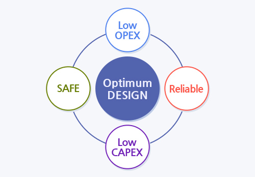
will provide the most economical and the most reliable package system to customer.
Reinforcement of regulations for the conservation of the marine atmosphere by IMO, under the UN
1997 MARPOL Protocol : SECAs ( ECAs)
| Baltic Sea | Adopted 1997/ into force 2005 |
|---|---|
| North Sea | Adopted 2005/ into force 2006 |
| North American coasts | Adopted 2010 / Into force 2012 |
| US Caribbean Area | Adopted 2011 /Into force 2011 |
| Outside an ECA | Inside an ECA |
|---|---|
| 4.5%prior to 1.Jan. 2012 | 1.5%prior to 1.July. 2010 |
| 3.5%on & after 1.Jan. 2012 | 1.0%on & after 1.Jul. 2010 |
| 0.5%on & after 1.Jan. 2020 | 0.1%on & after 1.Jan. 2015 |
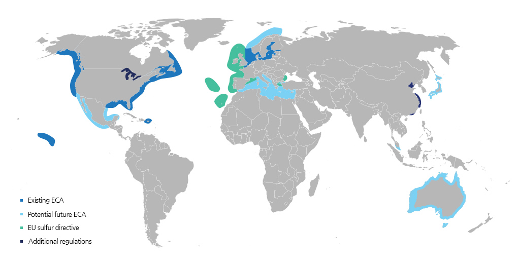
Existing ECA zones and possible future ECAs
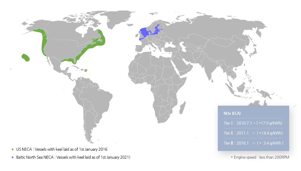
NOx Emission Control Areas (NECA)
Initial IMO strategy on Reduction of GHG emissions from ships
| Level of ambition | Timeline |
|---|---|
|
Carbon intensity of ships to decline
|
Short-term measures: 2018–2023
|
|
Carbon intensity of shipping to decline
GHG emission from shipping to decline
|
Mid-term measures: 2023–2030
Long-term measures: > 2050
|
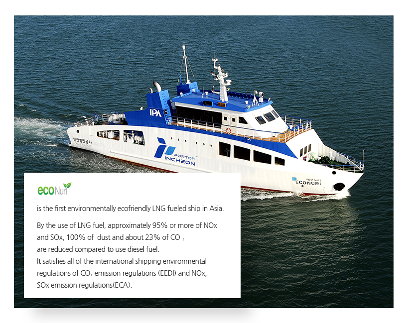
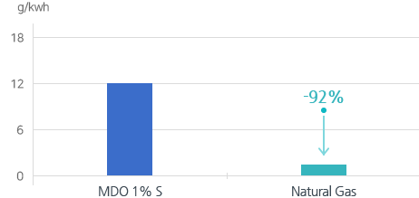
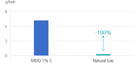
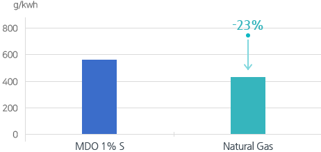
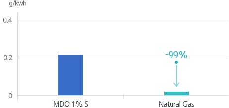
By using Natural Gas Instead of MDO, CO2 is reduced about 23% and SOx, NOx and PM are reduced more than 92%.
* Source: Marintek Report from Rolls-Royce DF Engine
-
NOx
-
SOx
-
CO2
-
Particulates
-
Total Package Service for Engineering & Supply
- Full package for Engineering FGSS and FGSS equipment
- Turn key delivery of FGSS including S&SYS’s own control system (AMS, ICMS, IAS) -
Engineering Support with Proven Technology and Operating Experience for various vessels
- Reliable Engineering based on Reference and site experience in various of FGSS project.
- Post docking operation with N2 , Bunkering operation, Pre-docking operation, Gas trial. -
Engineering Data for Ship Design Relevant to FGSS
HAZID, HAZOP / FMEA / Cause & Effect / FAT procedure / SAT procedure/ Gas trial procedure FDS(Functional Design Specification) /
Tank preservation procedure/ Operation & Maintenance manual/ Double pipe drawing, etc. -
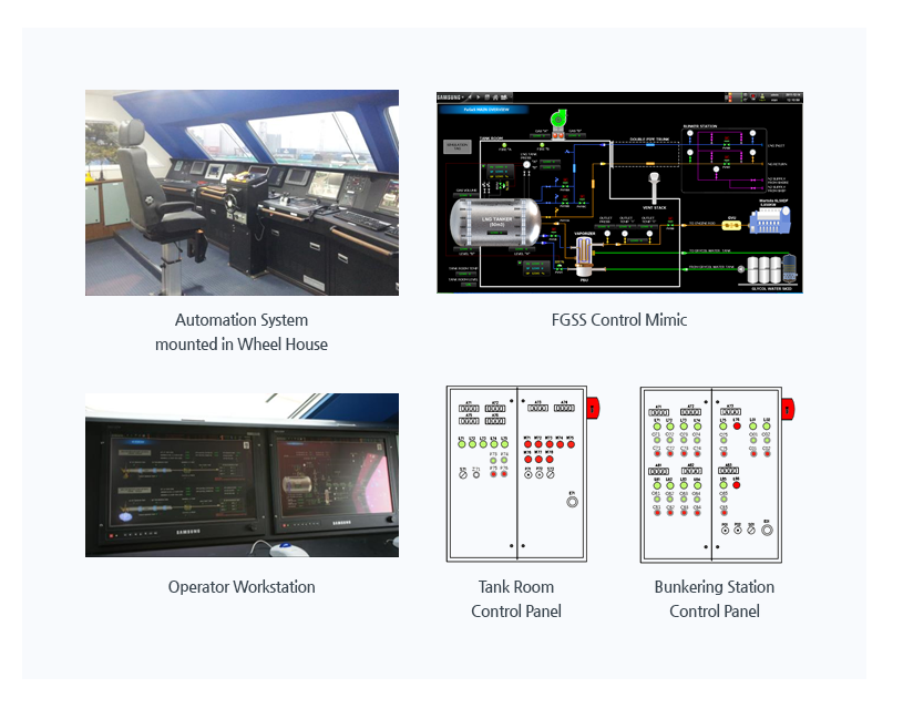
Particular FGSS Control System for High Performance
- Strong & Reliable Hardware
- Providing Diagnostic Mimic of Automation System
- Providing Logic Programming Tool for Function & Sequential Flow, Real Time Monitoring
- Easy Maintenance with Search function, Change alarm set value
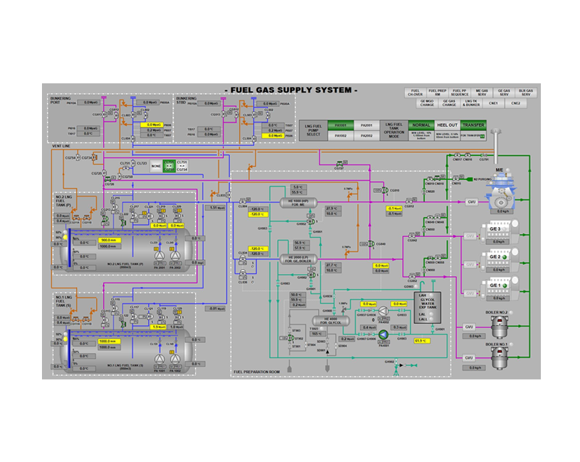
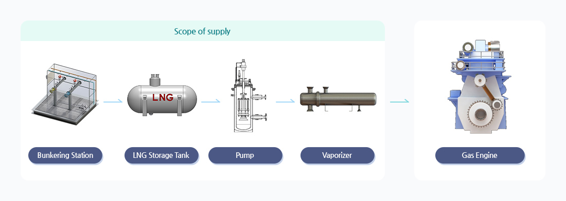
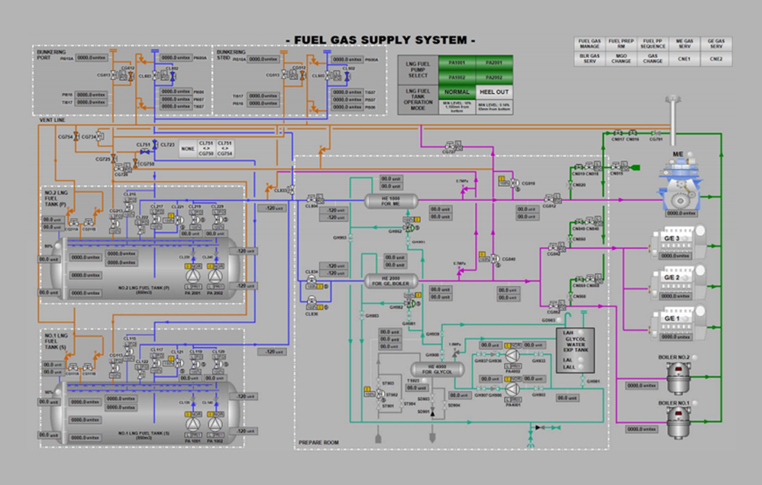
Flow Diagram
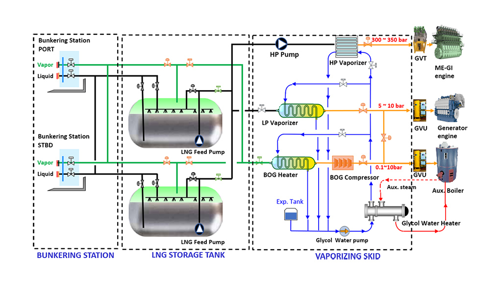
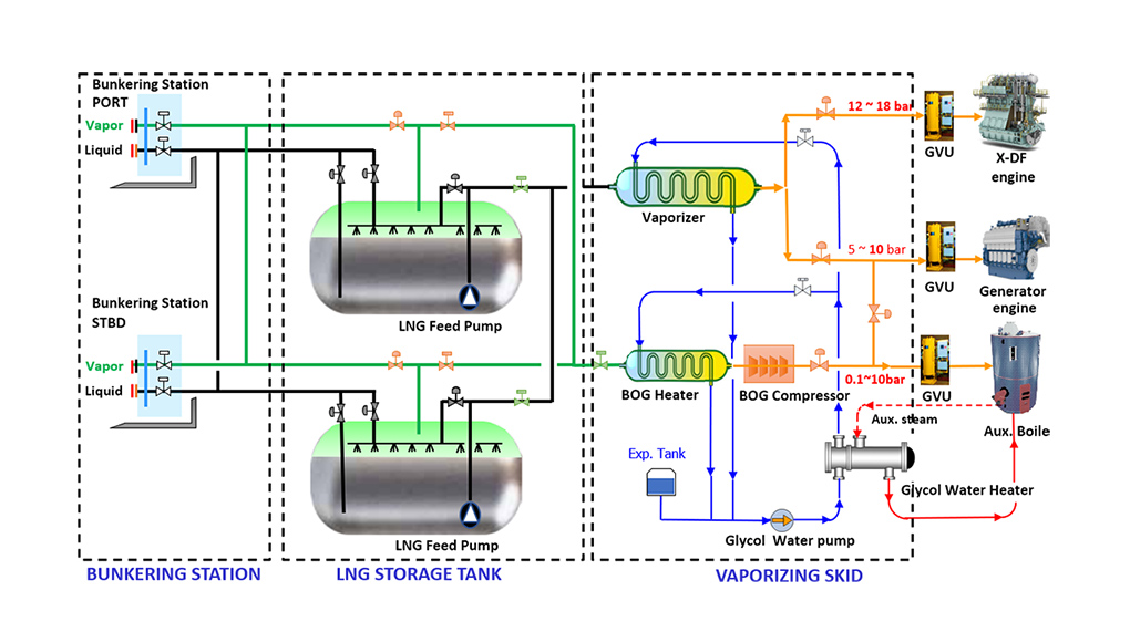
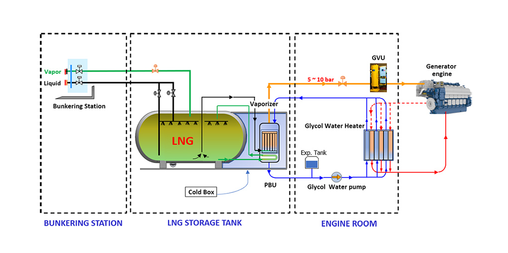
Major Equipment
-
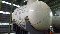
LNG Storage tank
-
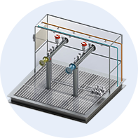
Bunkering Station
-
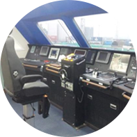
Control & Monitoring system
-
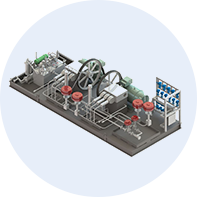
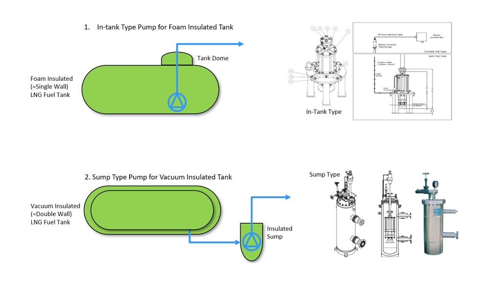
H.P. Pump Skid
-
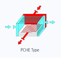
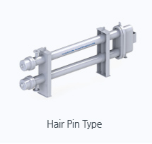
Vaporizer Skid
-
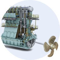
Engine
- 1. Quantity: 2 sets ( Port & Starboard shipside)
- 2. Liquid Line: 4 ~ 8” Pipe
Vapor Line: 4 ~ 6” Pipe
- 3. Dimension ( In accordance with SGMF guidance )
- Distance of manifold flanges inboard from ship’s side. : 1,100mm
- Horizontal distance between flange centers : 1,250 mm
- Vertical distance between flange center & working platform : * mm
( * depend on ship’s specification )
| IMO Classification of LNG Carriers( IGC Code) | |||
|---|---|---|---|
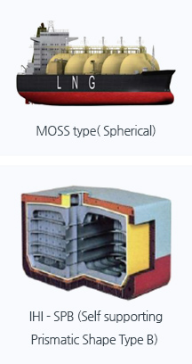
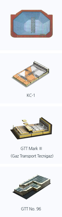
| Independent Tanks (separated from hull structure) | Integrated Tanks (part of hull structure) | ||
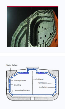
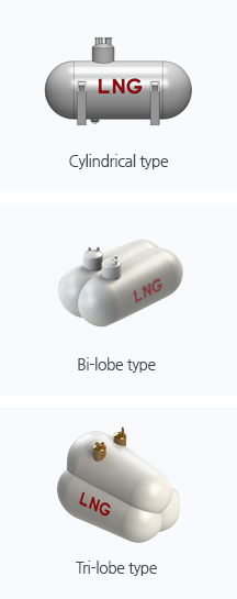
| Type A | Type B | Type C | Membrane Tank |
|
* Simple Design * Pο ≤ 0.7 bar * Full secondary barrier |
* Flat Design * Pο ≤ 0.7 bar * Partial secondary barrier |
* Simple Design * Pο ≥ 2 bar * No secondary barrier |
* Simple Design * Pο ≤ 0.7 bar * Full secondary barrier |
 |
 |
 |
 |
-
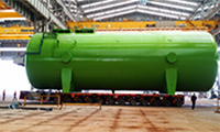
Double shell with Vacuum
-
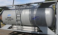
ISO container (20ft, 40ft)
-
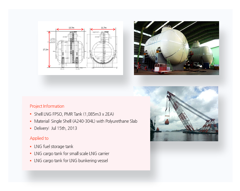
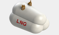
Single shell with PU
-
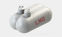
Bi-lobe Tank
-
Tri-lobe Tank
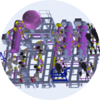
| High Pressure Vaporizer | Low Pressure Vaporizer | ||
|---|---|---|---|
|
|
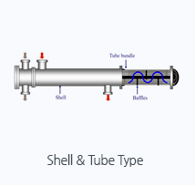
|
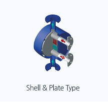
|
Reference
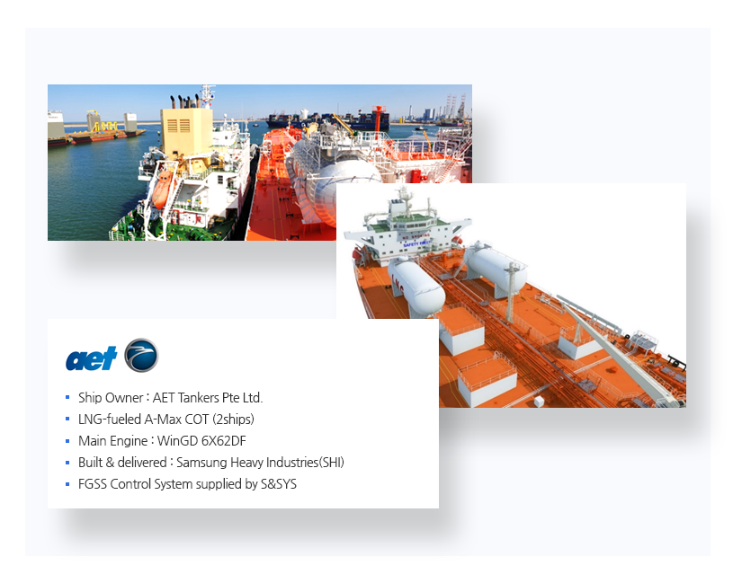
Control system A-Max COT FGSS
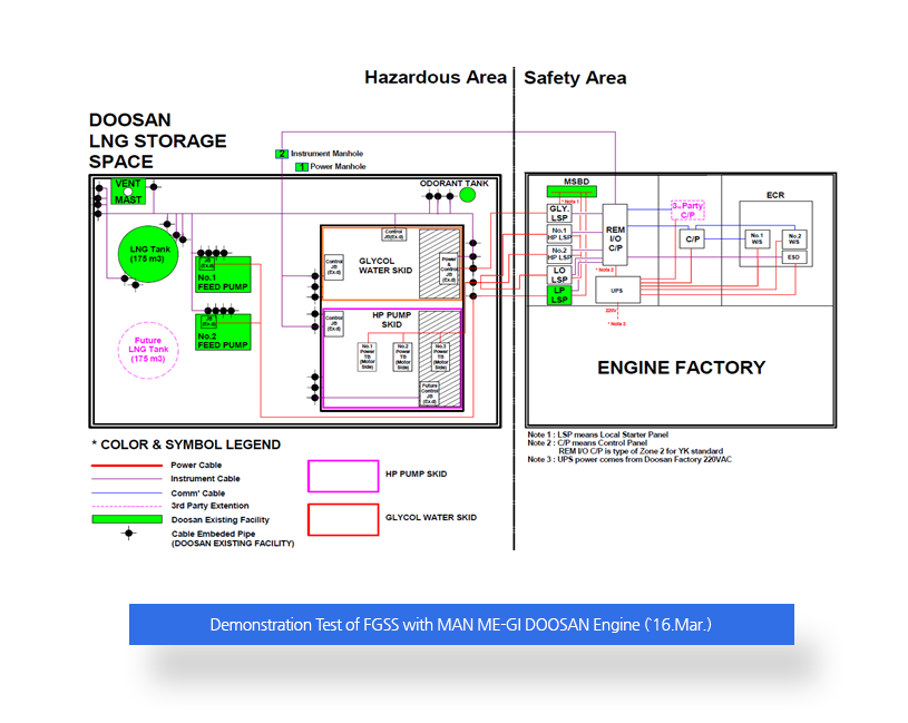
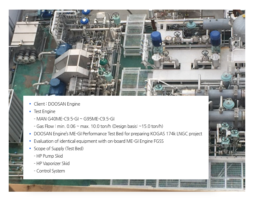
Control system MAN ME-GI
Engine Test Bed
- Control system MAN ME-GI
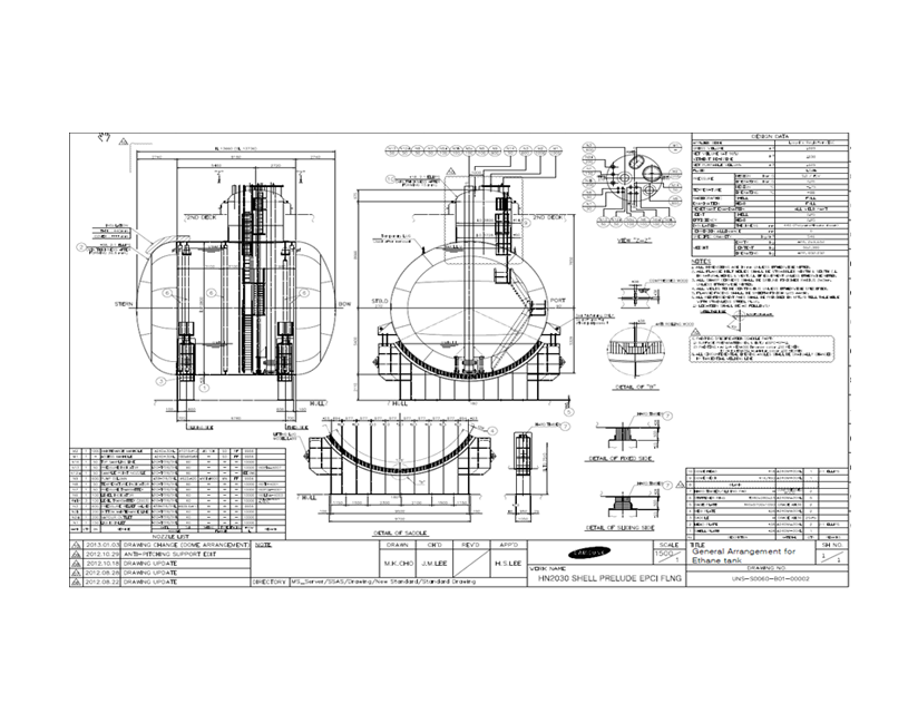
Engine Test Bed Storage Tank
PMR(Pre-cooling
Mixed Refrigerant)
Tank Storage Tank
PMR(Pre-cooling
Mixed Refrigerant)
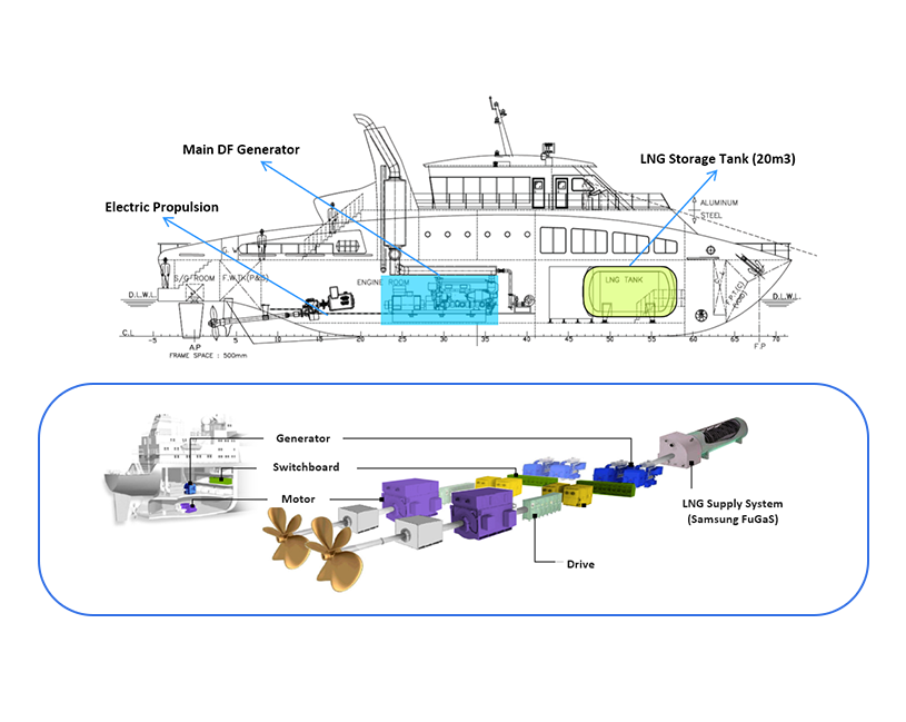
Tank EcoNuri
Automation
System EcoNuri
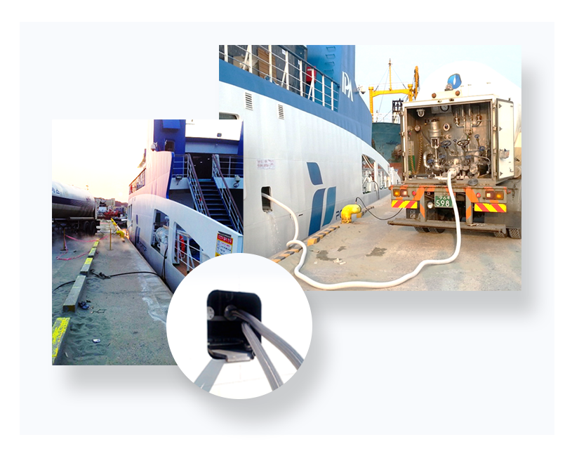
Bunkering
of EcoNuri EcoNuri
General
Arrangement EcoNuri
1st LNG fueled
ship in ASIA Ship Particular 1.GT : about 200Ton
2.LOA : about 38m
3.LBP : about 34m
4.Breadth : 8.0m
5.Draft : 2.1m
6.Speed : abt. 15 knot
7.Passenger : abt. 57 persons